- Introduction
- What is included in the kit?
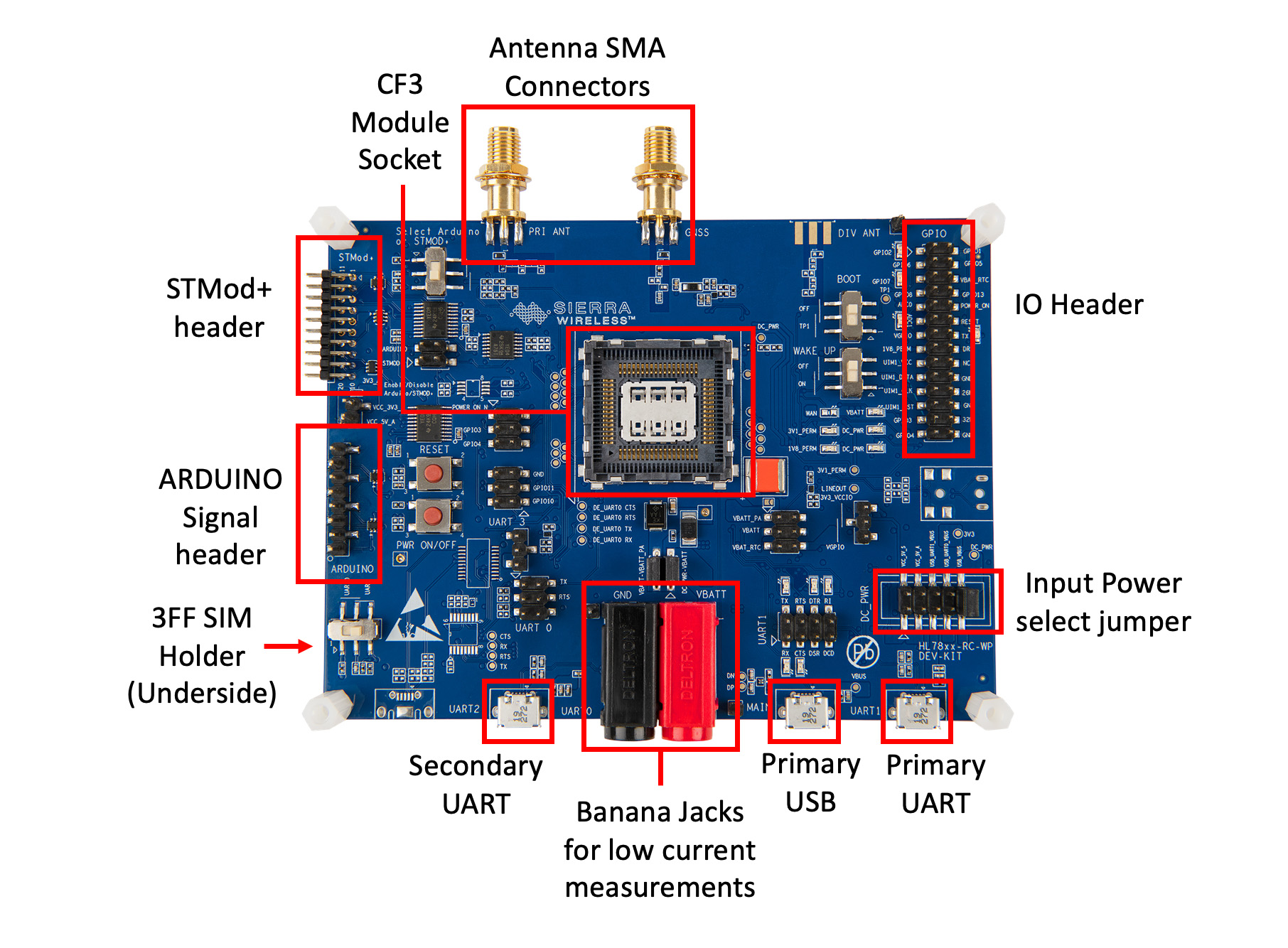
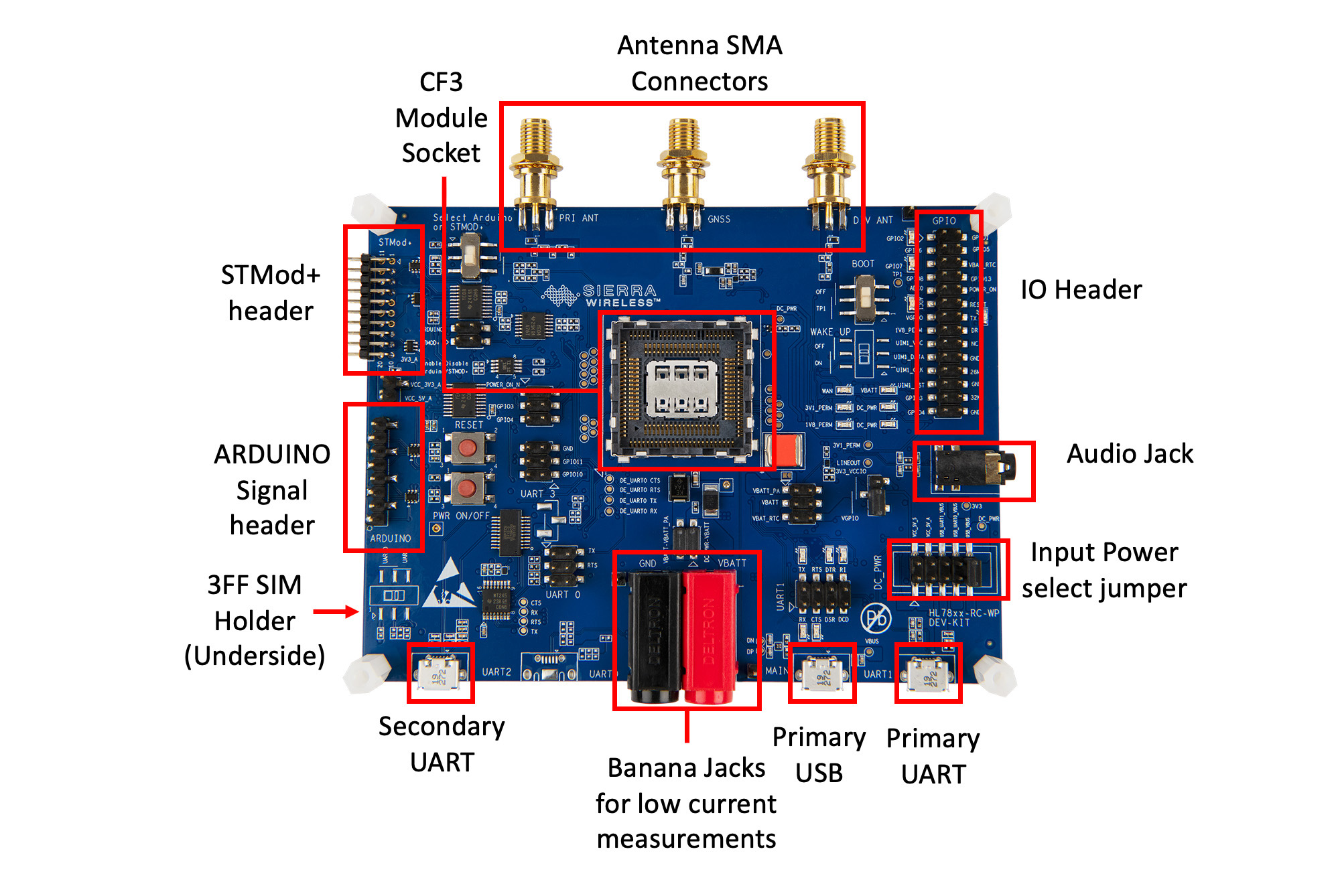
- Board overview
- What else do you need to start?
- Select your kit to get started
- Getting started with the HL78 Evaluation Kit
- Performing Low Power Mode Current Measurements
- Testing Extended Discontinuous Reception (eDRX) Mode
- Testing Power Saving Mode (PSM)
- Getting started with the RC76 Evaluation Kit
Welcome to the HL78 and RC76 Evaluation Kits – your gateway to seamless integration and easy testing of the HL78xx and RC76xx modules with your solutions. Designed with developers in mind, these user-friendly evaluation kits provide hassle-free setup and connectivity, empowering you to create innovative IoT solutions. Let's dive in and get started! 🚀
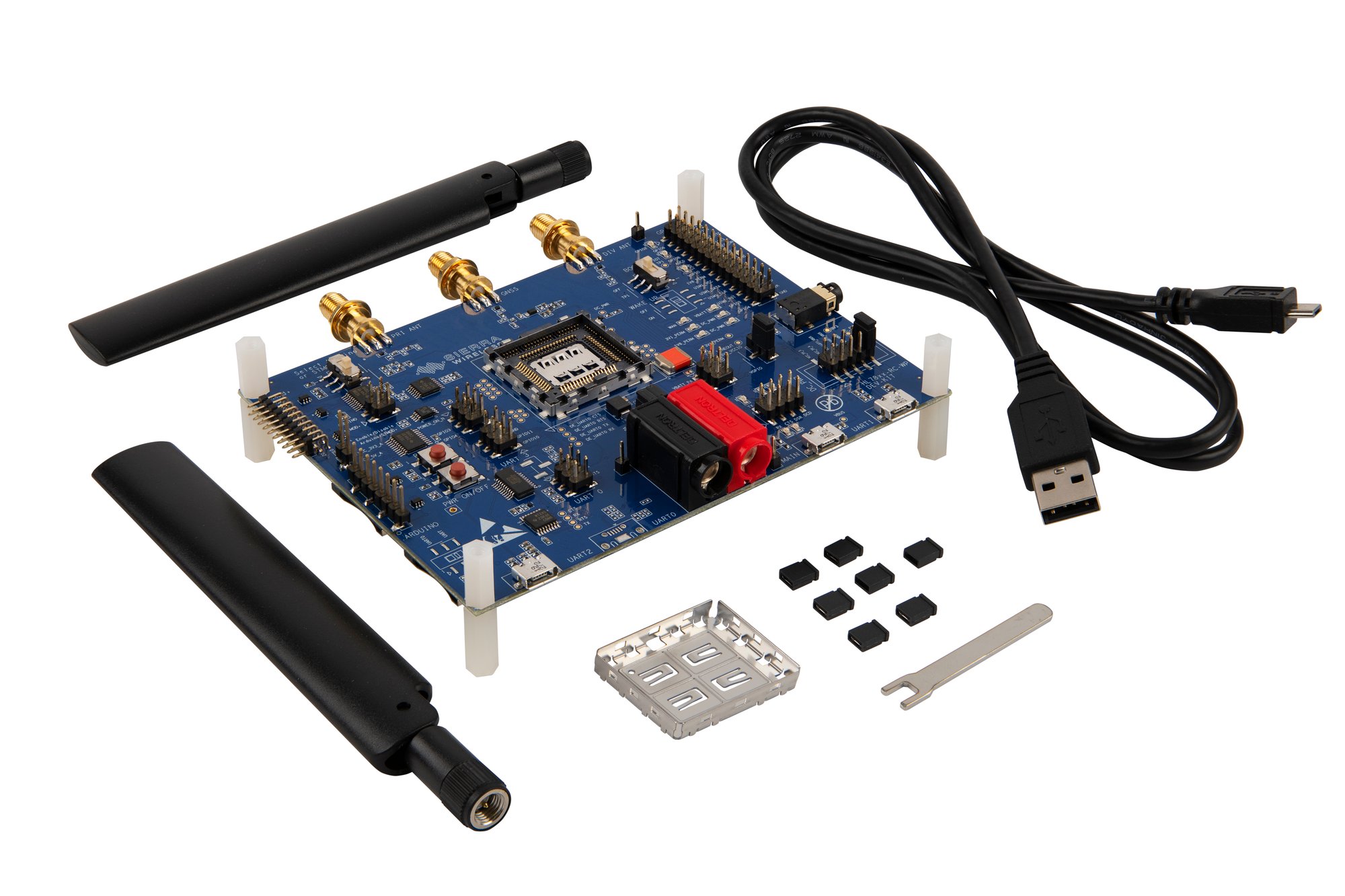
- 1 board
- Antenna (2 for the RC76 kit, 1 for the HL78 kit)
- 1 USB cable
- 1 lid
- 1 removal tool and some jumpers
- 1 interposer for the HL78 kit only
HL78 Evaluation Kit
RC76 Evaluation Kit
You will need a compatible module, a working SIM card and a PC with PuTTY (or similar application) installed for connecting with your board.
- Compatible module:
- For the HL Series: HL7800, HL7802, HL7810, HL7812, HL7845
- For the RC Series: RC7611, RC7620, RC7630. The kit can also be used with the WP76xx modules.
- A SIM card (in 2FF/Mini SIM form factor) that connects to a local cellular network.
- If your Evaluation kit came with a Sierra Wireless SIM card. Click below button to activate your trial offer.
Which Evaluation Kit do you have?
Welcome to the HL78 module getting started guide. This guide will help you set up the evaluation kit (eval kit) for sending AT commands to the HL78 module and initiating data transmission. It is divided into four sections:
- Setting Up the Hardware
- Updating Firmware to the Latest Version
- Checking Your Basic Configurations in PuTTY
- Establishing a Data Connection through TCP
- Further Reading
1. Setting Up the Hardware
1) Module Installation
Position the HL78xx module at the center of the socket. Use the included interposer for this step and secure the module by snapping on the provided snap-in cover. Please ensure the visible dots on the socket, module, interposer, and snap-in cover are aligned to the bottom left corner. In case of incorrect installation, use the provided wrench to loosen the cover and reposition the module.
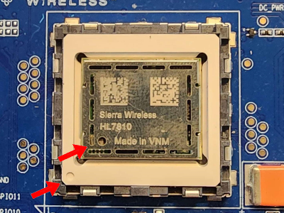
Figure 1: An HL7810 module correctly Installed
2) Board Configuration
The board should be configured out of the box for operation. If not, use the jumpers from the provided bag to configure the board as shown in the figure below. Pay attention to the boxed locations on the board and ensure that they are the same. Install on the following jumper/switch settings:
- Ensure the WAKE-UP signal is set to the OFF position on switch SW203
- CN401 (pins 1 and 2) - Enable UART1 via USB
- CN301 (pins 1 and 2) – Enable UART0 via USB for debugging
- CN805 (pins 5 and 6) – Set board power to USB_UART1_VBUS
- CN1301 – Connects VBATT to VBATT_PA and DC Power
- CN1310 – Enable DC Power
- CN1308 & CN1309 - connects isolating capacitors to the power lines
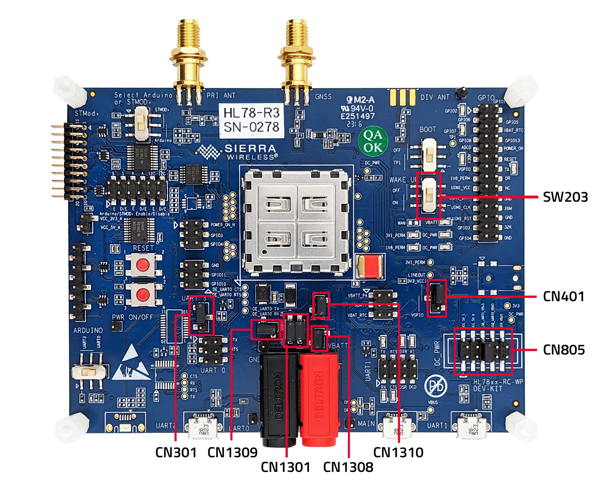
Figure 2: Top view of the eval kit with correct jumper placement
3) Antenna Installation
Connect the provided RF antenna to the left connector (marked as PRI_ANT)
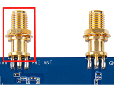
Figure 3: RF and GNSS antenna connectors
4) SIM Card Installation
Insert a SIM card into the designated SIM slot, CN500. You might find it easier to do this by turning the board over to access the SIM slot.
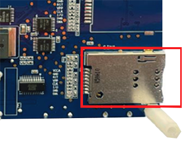
Figure 4: The SIM slot
5) Eval Kit-PC Connection
Use the provided micro-USB cable to connect the eval kit to a PC via UART1. This connection will also power the board. You should see some LEDs light up at this point.
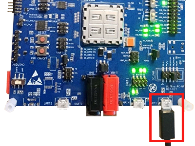
Figure 5: An eval kit connected with a micro-USB cable via UART1
6) COM Port Assignment
Open your Device Manager to find out what COM port is assigned to the eval kit. Then, launch PuTTY (or similar application) and fill in the parameters as shown in the figure below. (For example, we’ve used COM8).
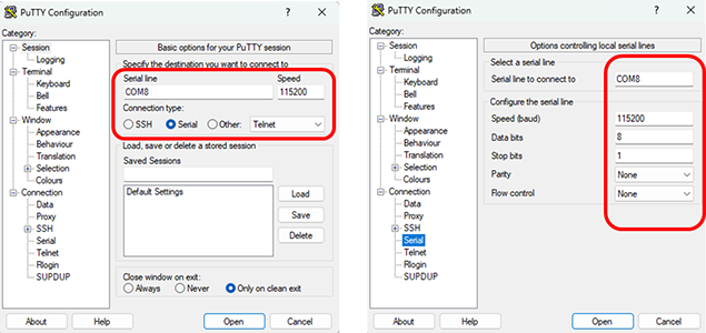
Figure 6: PuTTY Configuration of the correct parameters
7) Terminal Setup
Click ‘Open’ to open the terminal. Type ‘at’ into the terminal. If the terminal responds with ‘OK’, then the hardware setup is successful, and you are ready to use AT commands with the eval kit.
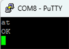
Figure 7: PuTTY terminal showing successful connection to the eval kit
2. Updating Firmware to the Latest Version
You can check if it is based on the HL78xx page from the Source. If you do have the latest version, you may skip this section. If you do not know what version you have, type ‘ati’ into the terminal.
1) Download .exe file from the Source
Download the applicable .exe file from the page above.
2) Change Parameters in Terminal
- Open the Command Prompt.
- Redirect to the location of your .exe file.
- Set the DL_PORT to your COM port currently connected to your computer (in this example, it is COM6).
- Set the DL_BAUD to 3000000.
C:\Users\xyz\Downloads>set DL_PORT=COM6
C:\Users\xyz\Downloads>set DL_BAUD=3000000
*xyz = Username in the HL78 Firmware Update section
3) Execute the .exe file
Finally, execute the .exe file by typing it in the terminal (i.e., “HL7810.5.4.12.3.exe”) and watch the program update your firmware to the latest version!
3. Checking Your Basic Configurations in PuTTY
Before attempting to establish a TCP connection in PuTTY, it is important to review the following list of basic AT commands. For reference, all AT commands for the HL78xx modules can be found in the Source.
| • AT+CEREG? | Confirms EPS Network Registration (The second value should be 1 or 5 which confirms that it is working) |
| • AT+KCARRIERCFG? | Returns the current Mobile Network Operator setting. This should match the SIM you are using. Use generic if one doesn’t exist for your SIM. Set AT+KCARRIERCFG=15 if you are using a Sierra Wireless SIM card. |
4. Establishing a Data Connection through TCP
This section of the guide will explain how to send IP data using your HL78xx module. We’ll use the internal TCP client of the module to connect to a TCP server on the internet. Once a connection is established, both server and client can send and receive data in any order. The next few steps will guide you on configuring the TCP connection, initiating the connection, sending data, and receiving data
For this example, we are using a Semtech TCP server located at flake.legato.io that operates on port 6000.
1) TCP Connection Configuration
Start by setting up the TCP connection. This involves setting the IP address and port number with the command AT+KTCPCFG=(1,0,IP_address,port_#). For this example, we are using a:
at+ktcpcfg=1, 0, "flake.legato.io", "6000"
You will receive a response indicating your session number:
+KTCPCFG: 1
2) Start TCP Connection
Now that you have a session number, you are ready to initialize the connection using the command AT+KTCPCNX=(session_id):
at+ktcpcnx=1
A successful connection will be signified by a response as follows:
+KTCP_IND: 1, 1
3) Send Data Through a TCP Connection
With a successful connection, you can send data by enabling data mode with the command AT+KTCPSND=(session_id, number of bytes you want to send through):
at+ktcpsnd=1, 1
The terminal will then respond with “CONNECT”.
CONNECT
Once you see this, you are now in data mode; any text you input will be the data you send. Type the message that you want to send through the terminal.
Note: The text might appear invisible, but it will be transmitted. Once done, type +++ to exit data mode. The terminal will revert to normal and acknowledge the exit with a simple “OK”.
Once you exit data mode, you will get a message indicating how many bytes of data the module has received from the server and are ready to be retrieved.
+KTCP_DATA: 1,1
In this example, this notification means that you can receive 1 byte from session 1. Your message may be comprised of multiple +KTCP_DATA notifications.
4) Receive Data Through a TCP Connection
With a successful connection, you can receive data from data mode with the command AT+KTCPRCV=(session_id, number of bytes you want to receive):
at+ktcprcv=1, 1
The terminal will then echo back the text you sent from the previous step and finish with an “OK”.
5) Server Closes the Connection
After a period of inactivity, the remote server will close the connection. You will see the following notification:
+KTCP_NOTIF: 1, 4
Please refer to the following figure for a complete illustration of the entire process in the terminal.
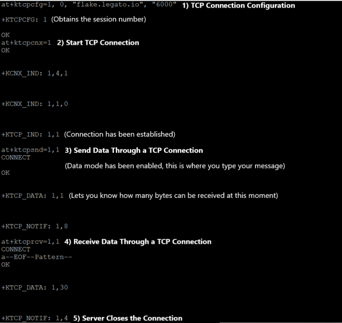
Figure 8: PuTTY terminal showing how to send data through TCP connection
5. Further Reading
Congratulations! By now, your HL78 module should be up and running, ready to connect your solution's data across the globe. To learn more about the HL78 evaluation kit, please refer to the User Guide in our Documentation Center. We sincerely appreciate your decision to choose our HL78 module!
This section of the guide will instruct you how to configure the evaluation kit and module in order to perform low power mode current measurements. It covers the hardware setup and settings for eDRX and PSM modes.
1. Hardware Setup
1) Board Configuration
Assuming you have already installed the jumpers from the “Getting Started with the HL78 Evaluation Kit”, you will need to remove several jumpers before starting. Removing these jumpers will allow the board to be powered by USB but the module to be powered by an external source (e.g. the Otii). Remove the following jumper settings:
- CN1301 (1 & 2) – Separates module and dev board power rails (Note: ONLY remove the right jumper of the two.)
- CN1308 & CN1309 - Disconnects isolating capacitors from power lines
- CN1310 – Disables DC Power

Figure 9: Top view of the eval kit before jumper removal
2) Connect Otii to Dev Kit Board
Assuming you have access to an Otii, plug it into a wall outlet and connect it to your computer through USB. You also need to connect it to your dev kit board through banana jacks.
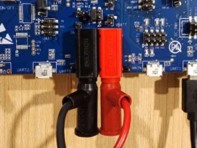
Figure 10: Banana jacks connected between the dev kit board and the Otii
3) Turn the WAKE_UP Pin ON
Ensure that the WAKE_UP pin on your dev kit board is switched to ON:
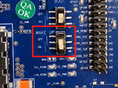
Figure 11: This WAKE-UP pin set to ON
The following part of the guide will instruct you on how to configure the HL78 module to operate in hibernate mode with eDRX (extended Discontinuous Reception) enabled.
1) Deactivate Power Modes
Open PuTTY to begin sending AT commands. First, deactivate the power modes before enabling eDRX mode. For this example, we are using:
at+ksleep=2
2) Select Cat-M1
Select Cat-M1 as the LTE category. If the module is already in CatM1, an error will be reported. For this example, we are using a:
at+ksrat=0
3) Stop the Stack
It’s important to stop the stack beforehand. It is used to deactivate the cellular communication stack temporarily. For this example, we can use:
at+cfun=4
4) Deactivate PSM
It is required to deactivate Power Saving Mode (PSM) if it is currently on. PSM is a feature that allows a device to enter a low-power state when it's not actively communicating. We can type this command:
at+cpsms=0
5) Activate eDRX in Cat-M1
Finally, use this command which activates eDRX in Cat-M1. The at+cedrxs parameters are as follows: 1=activate eDRX, 4=use CatM1 technology, and 5=set the requested eDRX value to 81.92 seconds.
at+cedrxs=1,4,5
6) Activate Unsolicited Commands
Activate unsolicited commands related to network registration. Use this command:
at+creg=2
7) Enable Hibernate Mode
Enable Hibernate mode, with the ability to wake it up using the external WAKE_UP pin. Use this command:
at+ksleep=1,2
8) Start the Stack
Start the cellular communication stack, possibly after configuring the module for hibernate mode. Use this command:
at+cfun=1
9) Verify eDRX Activation
Before testing, confirm the activation of eDRX mode with specific values such as CatM1, requested and given eDRX values, and the assigned Paging Time Window (PTW).
at+cedrxrdp
The terminal should have a similar response to this:
+CEDRXRDP: 4, "0101" , "0101", "0011"
The parameters are defined as follows:
4 = CatM1 , 5 = Requested eDRX value (81.92sec), 5 = eDRX value given by the network (81.92sec) , 3 = assigned PTW (5.12 sec)
10) Toggle WAKE_UP Pin OFF
Once finished with the previous AT commands, toggle the WAKE_UP pin OFF to allow the module to enter hibernate mode.
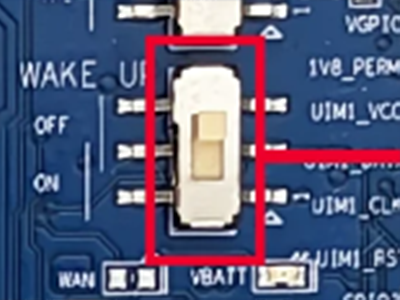
Figure 12: This WAKE-UP pin set to OFF
Your terminal should start responding like this:
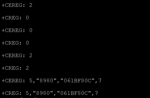
Figure 13: PuTTY terminal during eDRX mode
11) View Current Measures on OTII Software
After done setting up the module, open up Otii and start a new recording. Depending on which timer values are being used, let the OTII measure the current levels for twice as long as the timer values. You should see similar recordings to this:
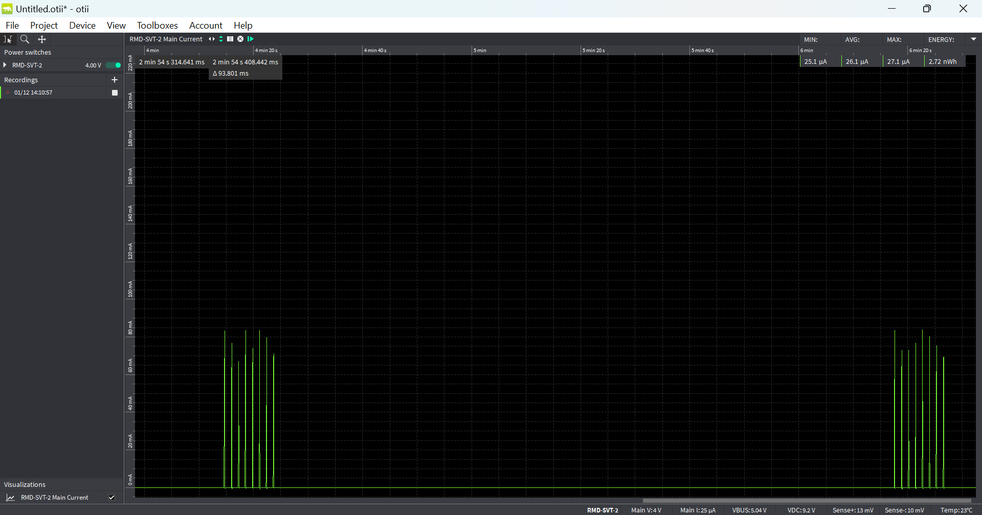
Figure 14: Otii current recording of HL78 during eDRX (In this example above, the timer values match up with the white line of being approximately 2 minutes)
This following part of the guide will instruct you on how to configure the HL78 module to operate in hibernate mode with PSM enabled.
1) Deactivate Power Modes
Open PuTTY to begin typing more AT commands. First, deactivate the power modes before attempting PSM. For example, we are using:
at+ksleep=2
2) Select Cat-M1
Select Cat-M1 as the LTE category. If the module is already in CatM1, an error will be reported. For this example, we are using a:
at+ksrat=0
3) Stop the Stack
It’s important to stop the stack beforehand. It is used to deactivate the cellular communication stack temporarily. For this example, we can use:
at+cfun=4
4) Configure PSM
Next, configure PSM using the command below. In this example, the values "10100001" and "00001111" represent the parameters for T3412 (1 minute) and T3324 (30 seconds), respectively. We can type:
at+cpsms=1,,,"10100001", "00001111"
NOTE: The network may not grant you the timer values requested. You may get a different value instead that is supported by the network (as seen in screenshot on step #9).
5) Activate Unsolicited Commands for EPS
Activate unsolicited commands related to EPS registration. We can use this command:
at+cereg=4
6) Enable network registration Unsolicited Result Codes
Enable network registration and location information unsolicited result code. We can use this command:
at+creg=2
7) Enable Hibernate Mode
Enable Hibernate mode, with the ability to wake it up using the external WAKE_UP pin. Use this command:
at+ksleep=1,2
8) Start the Stack
Start the cellular communication stack, possibly after configuring the module for hibernate mode. We can use this command:
at+cfun=1
9) Toggle WAKE_UP Pin OFF
Once finished with the previous AT commands, toggle the WAKE_UP pin OFF to allow PSM to start.

Figure 18: This WAKE-UP pin set to OFF
Your terminal should start responding like this:
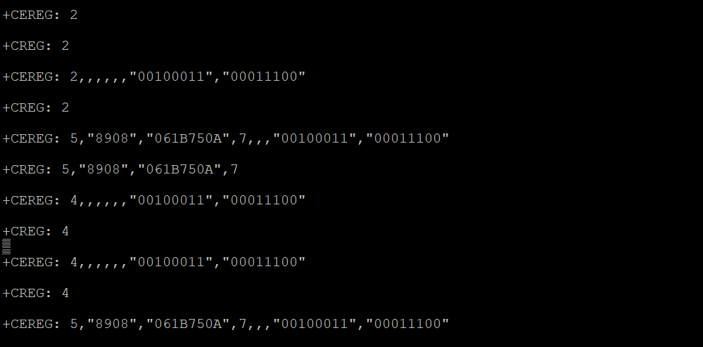
Figure 19: PuTTY terminal during PSM
10) View Current Measures on OTII Software
After done setting up the module, open up Otii and start a new recording. Depending on which timer values are being used, let the OTII measure the current levels for twice as long as the timer values. You should see similar recordings to this:
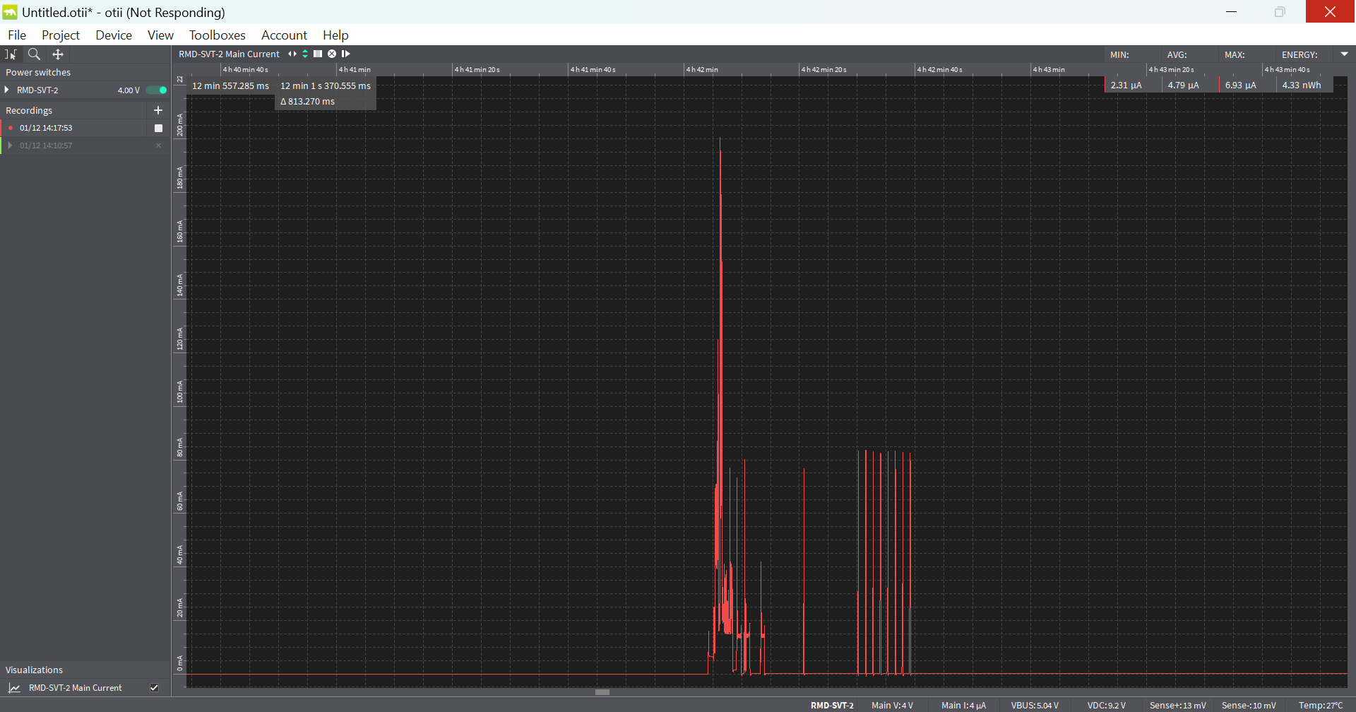
Figure 20: Otii current recording of HL78 during PSM
This is what it should look like when you zoom out even further:
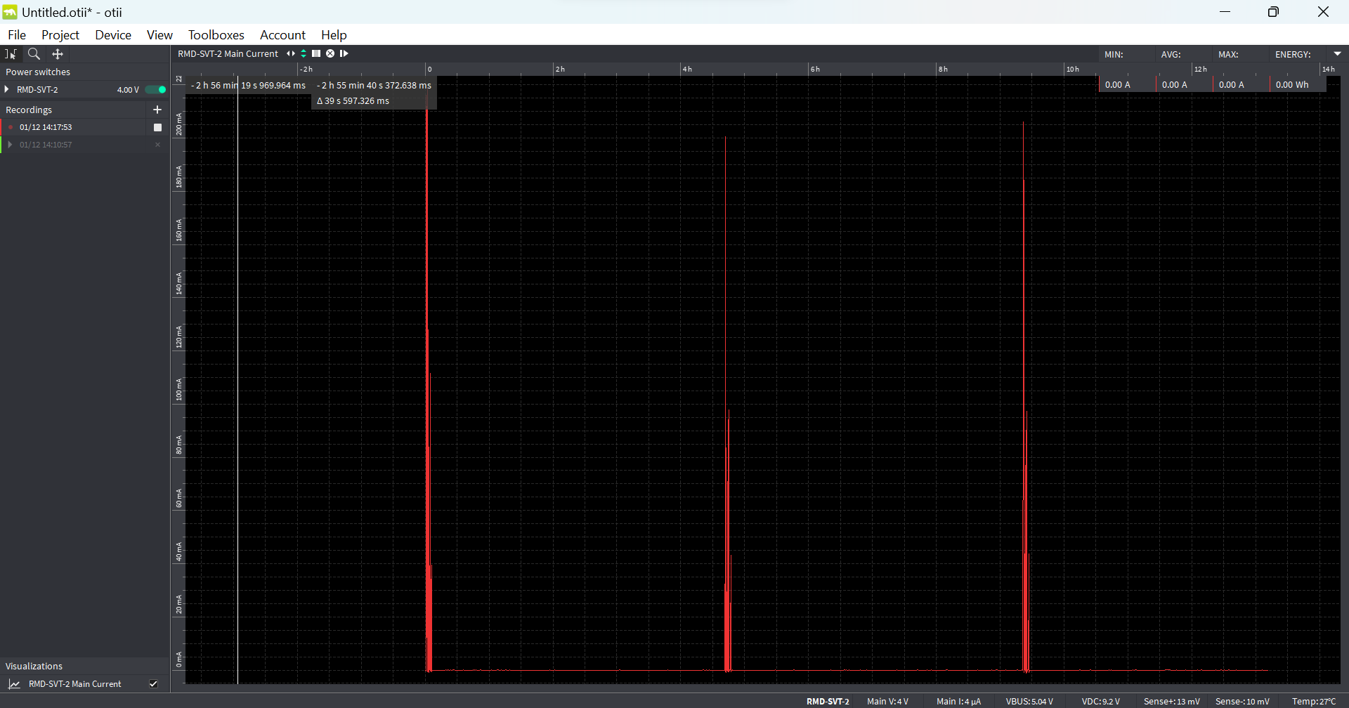
Figure 21: Another Otii current recording of HL78 during PSM (In this example above, the timer values match up with the white line of being approximately 5 hours)
Welcome to the RC76 module getting started guide. This guide will help you set up the evaluation kit for sending AT commands to the RC76 module and initiating data transmission. It is divided into four sections:
- Setting Up the Hardware
- Updating Firmware to the Latest Version
- Checking Your Basic Configurations in PuTTY
- Establishing a Data Connection through TCP
- Further Reading
1. Setting Up the Hardware
1) Module Installation
Position the RC76xx module at the socket. Then secure the module by snapping on the provided snap-in cover. Please ensure the visible dot on the socket, module, and snap-in cover, are aligned to the bottom left corner. In case of incorrect installation, use the provided wrench to loosen the cover and reposition the module.
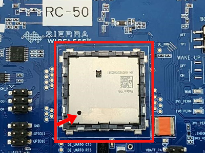
Figure 1: A RC76xx module installed with a snap-in cover on top
2) Board Configuration
The board should be configured out of the box for operation. If not, use the jumpers from the provided bag to configure the board as shown in the figure below. Pay attention to the boxed locations on the board and ensure that they are the same. Install on the following jump settings:
- CN401 (pins 1 and 2) - Enable UART1 via USB
- CN805 (pins 5 and 6) – Set board power to USB_UART1_VBUS
- CN1301 – Connects VBATT to VBATT_PA and DC Power
- CN1310 – Enable DC Power
- CN1308 & CN1309 - connects isolating capacitors to the power lines
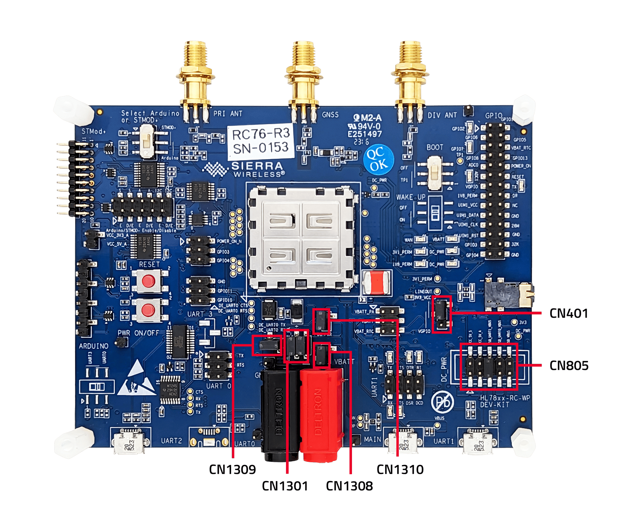
Figure 2: Top view of eval kit with correct jumper placement
3) Antenna Installation
Connect the provided RF antenna to the left & right connector. (marked as PRI_ANT and DIV_ANT)
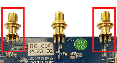
Figure 3: RF and GNSS Antenna Connectors
4) SIM Card Installation
Insert a SIM card into the designated SIM slot, CN500. You might find it easier to do this by turning the board over to access the SIM slot.
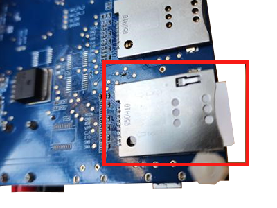
Figure 4: The SIM slot
5) Eval Kit-PC Connection
Use the provided micro-USB cable to connect the eval kit to a PC via UART1. This connection will allow the computer to interact with the board. You should see some of the LEDs light up at this point.
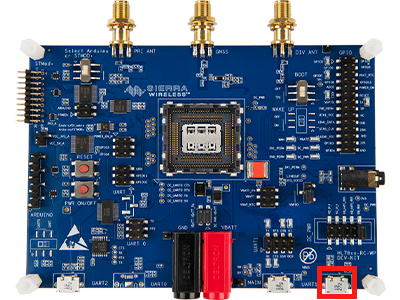
Figure 6: An RC76 eval kit connected with a micro-USB cable via UART1
6) COM Port Assignment
Open your Device Manager to find out what COM port is assigned to the eval kit. Then, launch PuTTY (or similar application) and fill in the parameters as shown in the figure below. (For example, we’ve used COM8).

Figure 7: PuTTY Configuration with the correct parameters.
7) Turn On the Module
Press the PWR button on the eval kit to turn on the module. This is important as the module will not work without this step.
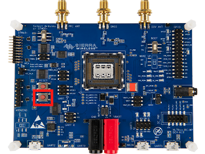
Figure 8: PWR ON/OFF button on RC76 eval kit
8) Terminal Setup
Click ‘Open’ to open the terminal. Type ‘at’ into the terminal. If the terminal responds with ‘OK’, then the hardware setup is successful, and you are ready to use AT commands with the eval kit.

Figure 9: PuTTY terminal showing successful connection to the eval Kit
2. Checking Your Basic Configurations in PuTTYUpdating Firmware to the Latest Version
You can check if it is based on the RC76xx page from the Source. If you do have the latest version, you may skip this section. If you do not know your version, type ‘ati’ into the terminal.
1) Temporary Board Reconfiguration
You will have to change one of your jumpers from when you set up the hardware. Instead of CN805 (pins 5 and 6), you will need to move this jumper to CN805 (pins 9 and 10). This will set the board power to USB_MAIN_VBUS.
2) Change USB cable from UART1 to MAIN
Because we now set power to USB_MAIN_VBUS, we will also have to put our USB cable in MAIN instead.
3) Download Latest Windows Drivers
For the latest Windows Drivers for RC76xx, go to the following Source page.
4) Download .exe file from the Source
Download the .exe file from the page at the beginning of this section for the mobile network carrier you are trying to connect to. If you are unable to find your corresponding mobile network carrier, then download the GENERIC file.
5) Execute the .exe file
Finally, execute the .exe file and watch the program update your firmware to the latest version!
6) Undo Board Reconfiguration
Move the jumper back to CN805 (pins 5 and 6). This will revert the jumper settings from USB_MAIN_VBUS to USB_UART1_VBUS once again.
3. Checking Your Basic Configurations in PuTTY
Before attempting to establish a TCP connection in PuTTY, it is important to review the following list of basic AT commands. For reference, all AT commands for the RC76xx module can be found in the Source.
| • AT!IMPREF? | Query (show) the preferred and current firmware plus carrier configuration pairs. Confirm that your carrier matches up with the AT command’s response as well as your SIM card. If not, use the AT!IMAGE command to list all available carriers. Next, use the AT!IMPREF=”[carrier]” command to set the image to your carrier. (If your carrier is not listed, use GENERIC). Then, use the AT!RESET command to reset the module afterwards. |
| • AT+CGDCONT? | Setting the AT!IMPREF from above should have set the proper PDP context data. You can verify if the APN is correct by using AT+CGDCONT?. Refer to the AT command guide if it needs to be updated. |
| • AT+CEREG? | Confirms EPS Network Registration The second value should be 1 or 5 which confirms that it is working. |
4. Establishing a Data Connection through TCP
This section of the guide will explain how to send IP data using your RC76xx module. We’ll use the internal TCP client of the module to connect to a TCP server on the internet. Once a connection is established, both server and client can send and receive data in any order. The next few steps will guide you on configuring the TCP connection, initiating the connection, sending data, and receiving data.
For this example, we are using a Semtech TCP server located at flake.legato.io that operates on port 6000.
1) Configure the IP Bearer
First off, we need to set some GPRS parameters that are needed before starting the TCP connection (i.e. APN, login, and password).
at+kcnxcfg=1,"GPRS","","log","password","IPV4","0.0.0.0","0.0.0.0","0.0.0.0"
2) TCP Connection Configuration
Start by setting up the TCP connection. This involves setting the IP address and port number with the command AT+KTCPCFG=(1,0,IP_address,port_#). For this example, we are using a:
at+ktcpcfg=1, 0, "flake.legato.io", "6000"
You will receive a response indicating your session number:
+KTCPCFG: 1
3) Start TCP Connection
Now that you have a session number, you are ready to initialize the connection using the command AT+KTCPCNX=(session_id):
at+ktcpcnx=1
A successful connection will be signified by a response as follows:
+KTCP_IND: 1, 1
4) Send Data Through a TCP Connection
With a successful connection, you can send data by enabling data mode with the command AT+KTCPSND=(session_id, number of bytes you want to send through):
at+ktcpsnd=1, 1
The terminal will then respond with “CONNECT”.
CONNECT
Once you see this, you are now in data mode; any text you input will be the data you send. Type the message that you want to send through the terminal.
Note: The text might appear invisible, but it will be transmitted. Once done, type +++ to exit data mode. The terminal will revert to normal and acknowledge the exit with a simple “OK”.
Once you exit data mode, you will get a message indicating how many bytes of data the module has received from the server and are ready to be retrieved.
+KTCP_DATA: 1,1
In this example, this notification means that you can receive 1 byte from session 1. Your message may be comprised of multiple +KTCP_DATA notifications.
5) Receive Data Through a TCP Connection
With a successful connection, you can receive data from data mode with the command AT+KTCPRCV=(session_id, number of bytes you want to receive):
at+ktcprcv=1, 1
The terminal will then echo back the text you sent from the previous step and finish with an “OK”.
6) Server Closes the connection
After a period of inactivity, the remote server will close the connection. You will see the following notification:
+KTCP_NOTIF: 1, 4
Please refer to the following figure for a complete illustration of the entire process in the terminal.
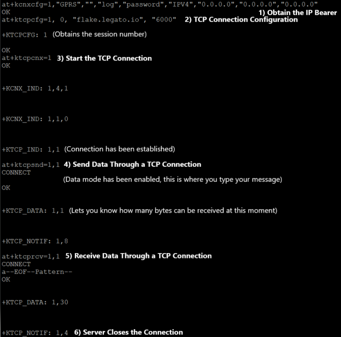
Figure 10: PuTTY terminal showing how to send data through TCP connection
5. Further Reading
Congratulations! By now, your RC76 module should be up and running, ready to connect your solution's data across the globe. To learn more about the RC76 evaluation kit, please refer to the User Guide in our Documentation Center. We sincerely appreciate your decision to choose our RC76 module!
Thanks again for choosing the HL/RC Evaluation Kit!
If you have any feedback or suggestions, please contact us.


